


The roller sorter belongs to one of the most common constructions that are currently applied in industry.
This sorting machines for grinding balls which are currently used on a large scale, allowing for achieving good results. Modern sorting machines, apart from sorting balls into appropriate dimensional classes, provide the possibility to reject grinding balls with a diameter below the limit value and to eliminate grinding balls the shape of which has been considerably deformed. Moreover, they enable the grinding balls’ surface to be initially cleared of impurities.

The roller sorter belongs to one of the most common constructions that are currently applied in industry. A diagram of this device has been presented in Fig. 1., Fig. 2 presents an example roller sorter.
This sorting machines for grinding balls which are currently used on a large scale, allowing for achieving good results. Modern sorting machines, apart from sorting balls into appropriate dimensional classes, provide the possibility to reject grinding balls with a diameter below the limit value and to eliminate grinding balls the shape of which has been considerably deformed. Moreover, they enable the grinding balls’ surface to be initially cleared of impurities.
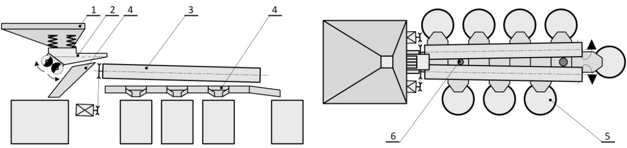
Fig. 1 Roller sorter diagram (side view – from the left, top view – from the right):
1 – hopper of the feeder, 2 – vibration feeder with grate, 3 – sorting roll,
4 – classification chute, 5 – bulk container, 6 – grinding ball
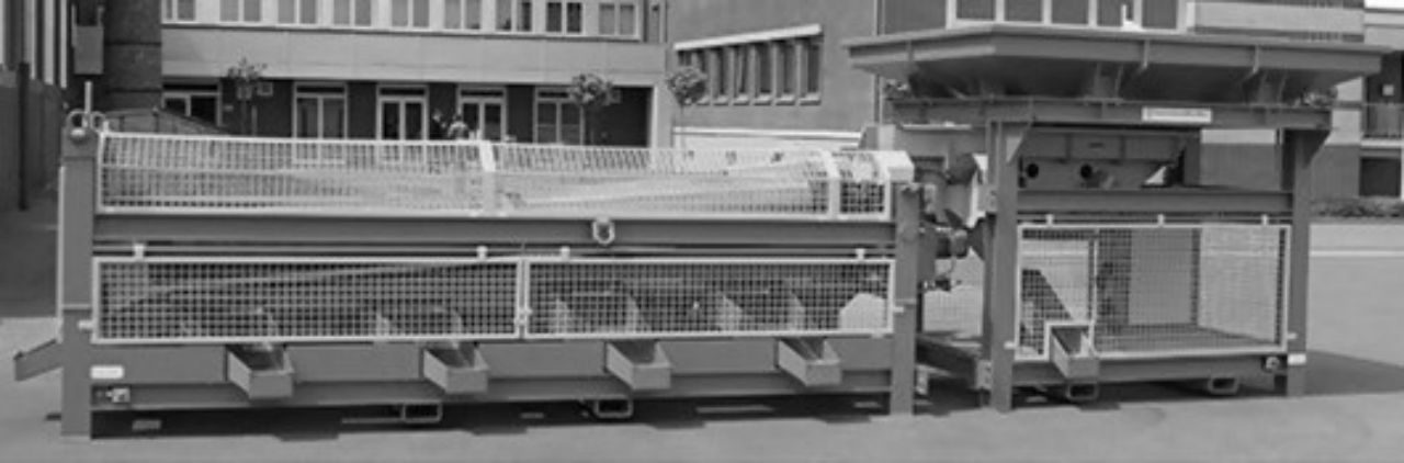
Fig. 2 A roller sorter without a support frame
The sorting process starts with filling the hopper, from which the grinding balls travel to the chute of the vibration feeder, most frequently characterized by linear motion. In newer constructions, the feeder chute is equipped with a special grate by means of which contamination in the form of dust, ground material remains, rust as well as small foreign bodies and grinding balls with dimensions considerably smaller than the limit ones are removed. From the feeder chute, grinding balls get onto the sorting rolls, which are responsible for the sorting process. The rolls’ axes are divergent from each other so as to create a gap between them, the width of which at the beginning of the assembly is set to the assumed minimal limit dimension, whereas at its end, it is set to the width similar to the dimension of the largest grinding balls subjected to sorting. Additionally, the rolls assembly is inclined by an appropriate angle to the basal plane in order to improve the grinding balls’ gravity movement. The concurrent rotational movement of the rolls prevents grinding balls from getting jammed in the gap and facilitates the movement of grinding balls with acceptable shape deformation along the cylinders. Owing to the divergent location of the rolls, at the beginning of the gap only grinding balls with the smallest diameter get through, whereas at its end – the ones with the largest diameter. The grinding balls getting through the gap in its particular segments find their way to appropriate classification chutes, by means of which they are delivered to bulk containers.
Some chutes are equipped with a flap closing the chute’s outlet, which allows for changing the bulk container without stopping the sorter. An example of such a automatic flap has been presented in Fig. 3.

Fig. 3 A flap closing the chute’s outlet diagram:
1 – classification chute, 2 – flap with weight, 3 – opening lever, 4 – bulk container
Only few constructions are additionally equipped with a subassembly responsible for improving the quality of sorting and rejecting the deformed grinding balls and foreign bodies. One of the examples is given in Fig. 4 and 5.

Fig. 4 A roller sorter with a belt conveyer and wheels

Fig. 5 A roller sorter with a heavy trailer
|
TECHNICAL DATA |
|||
|
CONTENTS |
UNIT |
PARAMETER |
|
|
PERFORNMANCE |
Roller diameter |
mm |
Φ150~250 |
|
Angle |
° |
0-12° |
|
|
Number |
set |
2/5 |
|
|
Roller length |
mm |
3200~6000 |
|
|
Balls diameter |
mm |
15-100 |
|
|
Design capacity |
t/h |
12/24 |
|
|
GEAR-MOTOR |
Model |
|
YSCL801-4 |
|
Power |
kW |
0.55 |
|
|
Speed |
r/min |
23-55 |
|
|
Quantity |
|
2/3 |
|
|
Vibrating feeder
|
MODEL |
|
GZ2F |
|
POWER |
kW |
0.22 |
|
|
Capacity |
T/h |
0-20t/h |
|
|
Discharge Size |
Groove width |
mm |
200 |
|
Quantity |
|
10 |
|
|
Spacing of roller |
Manual |
mm |
10-120 |
|
Supporting wheels |
diameter |
mm |
275 |
|
Quantity |
|
4 |
|
|
TRAVEL SPEED |
m/min |
5.3 |
|
|
OUTLINE DIMENSIONAL |
mm |
7910×1112/1915×2528 |
|
|
TOTAL WEIGHT (WITHOUT BALLS) |
t |
~8.5 |
|
|
MAXIMUM LOAD BALLS |
t |
~5.5 |
|
4.1Lubrication in bearing block of wheel group has been added in factory, and add again after running for 1500 hours.
4.2Smear enough lubrication on chain wheel and chain after a period of running or parking in order to lubricate and anti-rust.
Use maintenance free bearing on roller assembly.
|
No. |
Assembly unit
drawing No. |
part drawing
No. |
name |
Qty. |
|
1 |
TM3643 |
W6507010964 |
Bearing
BS2-2208-2CS/VT143 |
4 |
|
2 |
W6507020346 |
Bearing
SL045014-PP |
4 |
|
|
3 |
W4340100006 |
Single strand chain
16A-1 25.4 |
2m |
|
|
4 |
TM3646
/TM3647 |
W6507020348 |
Bearing
22217-E1 |
8 |


